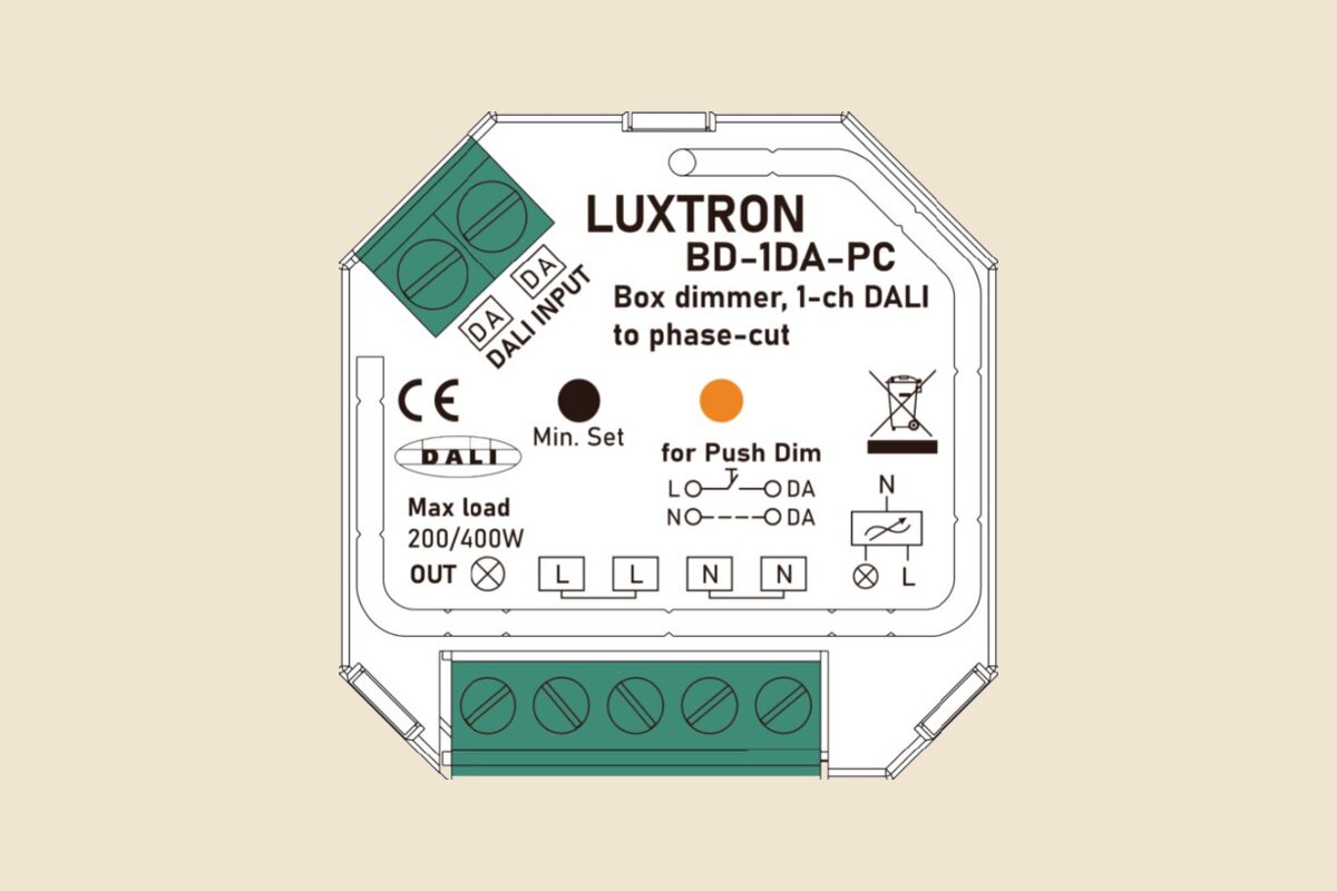
In March 2025 we added the BD-1DA-PC to our electronics range: a single-channel box dimmer that takes a DALI-2 signal on one side and gives a trailing-edge phase-cut output on the other. It exists for one job, getting mains-dimmable loads onto a DALI system without replacing the fittings.
Why a DALI to phase-cut dimmer
Most refurbishments in Dubai have at least a few circuits that will never see a DALI driver: decorative pendants, retrofit LED lamps, low-voltage halogen on electronic transformers. Rewiring them or changing the luminaires costs more than the rest of the controls package. The BD-1DA-PC sits between the DALI line and that circuit, so the load shows up as one more DALI address and dims with the rest of the room.
It registers as a single DALI address controlling one channel (device type 6), and the address is assigned automatically by the DALI master during commissioning. The datasheet lists compliance with IEC 62386-101, IEC 62386-102 and IEC 62386-207.
Loads and ratings
| Load type | Maximum at 230 V | Maximum at 120 V |
|---|---|---|
| Dimmable LED lamps | 200 W | 100 W |
| Dimmable LED drivers | 200 W | 100 W |
| Incandescent and HV halogen | 400 W | 200 W |
| LV halogen on electronic transformers | 200 W | 100 W |
Supply is 100 to 240 V AC, output current up to 1.8 A, and the MOSFET output dims smoothly down to 1 %. It is trailing edge only, so the connected lamps or drivers must support reverse phase control. That covers resistive and capacitive loads; check the lamp or driver datasheet before you assume.
The body is 45 x 45 x 20 mm, IP20, small enough to go inside a standard 86 x 86 mm wall box. DALI bus consumption is 2 mA at most.
Push-dim and minimum level
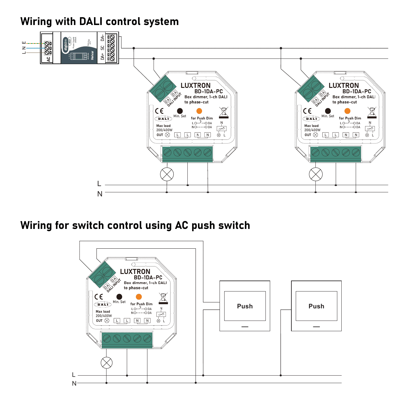
The DALI input terminals double as an 8 to 230 V AC switch input, so the same unit can run without a DALI system at all. One press switches the light on or off, holding the button dims up or down.
Cheap retrofit lamps often flicker at the bottom of the curve. The Min. Set button fixes that on site: dim to the lowest level that still looks stable, hold the button until the light flashes, and the dimmer will not go below that point again. To clear it, go to full output and press the button once more.
Installation limits worth knowing
- Keep the cable from dimmer to drivers under 80 m, and the same for push switch to dimmer.
- No more than 10 drivers in parallel on one dimmer. Inrush current at switch-on can damage it beyond that.
- Input and output use screw terminals, and a status LED flashes whenever the unit receives a DALI command, which helps when you are hunting for an address.
The full datasheet with wiring for low-voltage push buttons is on the BD-1DA-PC product page. For the rest of the DALI side of a project, see our lighting controls, or send us the circuit schedule and we will tell you which loads it can take.